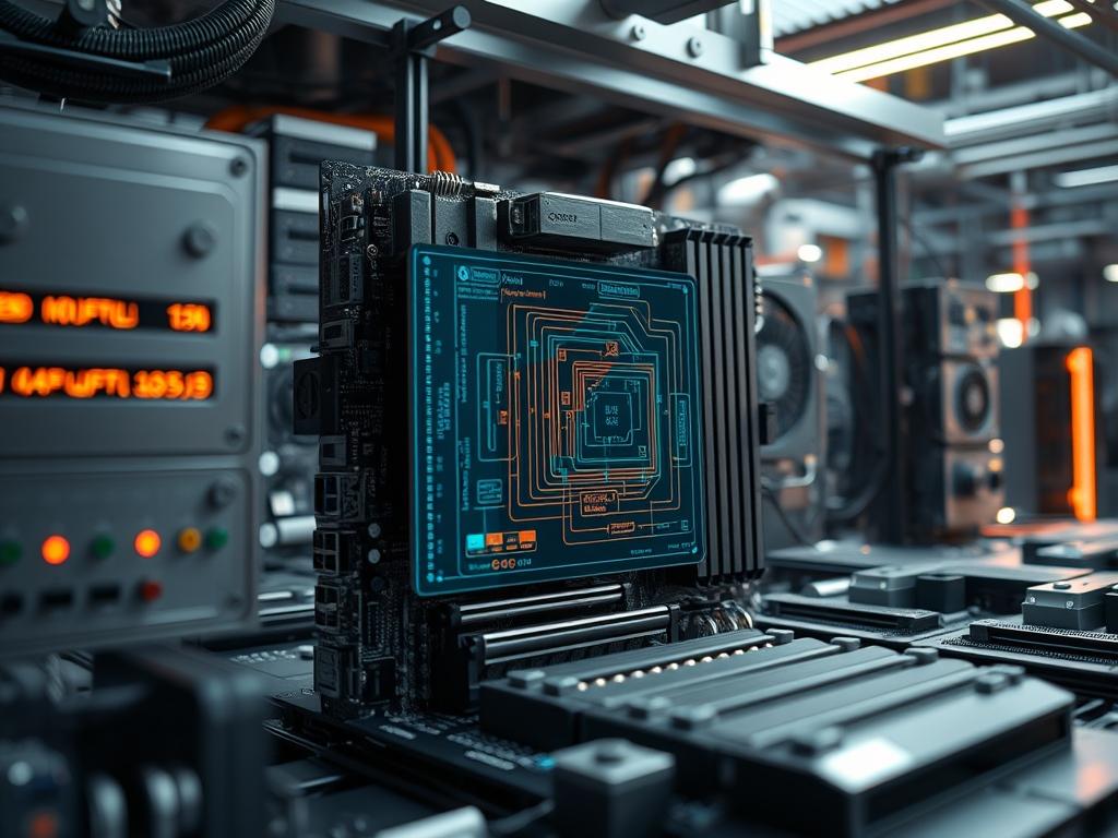
Workstation grade motherboard VRMs act as the primary power conversion layer between the high voltage output of a switching power supply and the low voltage, high amperage requirements of high performance silicon. In the context of modern cloud infrastructure and local compute clusters, these modules are the most critical components for ensuring system stability under sustained, high concurrency workloads. The primary role of the Voltage Regulator Module (VRM) is to step down 12V DC power from the Power Supply Unit (PSU) to a precise Vcore voltage, often between 0.7V and 1.5V, required by the Central Processing Unit (CPU) or Graphics Processing Unit (GPU). This conversion process must occur with minimal latency and high efficiency to prevent excessive heat production. A failure in this subsystem results in immediate system crashes, data corruption, or permanent hardware degradation. By utilizing multi-phase architectures, workstation grade motherboards distribute the electrical load across several power stages, reducing the thermal load on individual MOSFETs and improving the overall longevity of the hardware stack.
Technical Specifications
| Requirement | Default Port/Operating Range | Protocol/Standard | Impact Level (1-10) | Recommended Resources |
| :— | :— | :— | :— | :— |
| Vcore Stability | 0.8V to 1.55V DC | Intel VR13.x / AMD SVI2 | 10 | High-Density Inductors |
| Switching Frequency | 300kHz to 1000kHz | PWM (Pulse Width Modulation) | 8 | Digital PWM Controller |
| Operating Temperature | 40C to 105C | Thermal Diode / I2C Monitoring | 9 | Heat-pipe VRM Heatsink |
| Input Connection | 12V EPS (8-pin/4-pin) | ATX12V v2.4+ | 7 | 16AWG Power Cables |
| Phase Count | 8+2 to 16+4 Phases | Interleaved Phase Logic | 9 | DrMOS / Smart Power Stages |
| Telemetry Interface | SMBus / PMBus | I2C / PMBus 1.3 | 6 | Baseboard Management Controller |
THE CONFIGURATION PROTOCOL
Environment Prerequisites:
Before auditing or configuring workstation grade motherboard VRMs, the system must meet the following hardware and software dependencies:
1. ATX 3.0 / EPS12V compliant PSU: Power delivery must be ripple-free within a 1 percent tolerance margin.
2. Active Airflow: Minimum 150 LFM (Linear Feet per Minute) over the VRM heatsink area to manage thermal-inertia.
3. Firmware Version: BIOS/UEFI must support AGESA or Microcode versions that allow for Load-Line Calibration (LLC) adjustments.
4. Monitoring Tools: lm-sensors on Linux or HWiNFO64 on Windows for real-time telemetry extraction.
5. User Permissions: Root or Administrator access to modify MSR (Model Specific Registers) or UEFI variables.
Section A: Implementation Logic:
The engineering philosophy behind workstation grade motherboard VRMs focuses on the concept of interleaving. Instead of a single power stage bearing the entire current load, the PWM Controller staggers the activation of multiple phases. This reduces the payload on any single MOSFET, allowing the system to handle massive spikes in demand without exceeding the safe operating area of the silicon. Effective power delivery relies on minimizing signal-attenuation along the traces of the Printed Circuit Board (PCB). By placing the VRM physically close to the CPU socket and using 2-ounce copper layers, engineers reduce the parasitic resistance that leads to voltage drop, also known as Vdroop. This design ensures that the throughput of the power delivery system matches the concurrency of the compute threads, maintaining a stable clock frequency under heavy AVX-512 or deep learning workloads.
Step-By-Step Execution
1. Initialize VRM Telemetry via I2C
Use the command modprobe i2c-dev followed by i2c-detect -y 1 to scan the management bus for the PWM Controller.
System Note: This action attaches the kernel driver to the I2C bus, allowing the operating system to communicate directly with the VRM controller to read current, voltage, and temperature data.
2. Configure PWM Switching Frequency
Access the UEFI/BIOS and navigate to Advanced Power Settings; locate the VRM Switching Frequency and set it to a fixed value, such as 500kHz.
System Note: A higher frequency improves the transient response time but increases the switching losses and heat; a lower frequency improves efficiency but may increase the output ripple.
3. Calibrate Load-Line (LLC)
Set the Load-Line Calibration to a mid-range level (e.g., Level 3 or 4) to compensate for Vdroop.
System Note: This modifies the internal resistance curve used by the PWM Controller to ensure that voltage remains constant even as the current demand increases from an idle to a full-load state.
4. Verify Thermal Throttling Thresholds
Execute sensors in the terminal to verify that the VRM Temp or MOSFET Temp is being accurately reported.
System Note: The kernel uses these values to trigger thermal-event interrupts; if the VRM exceeds its rated temperature, the CPU will be forced into a lower P-state to prevent hardware failure.
5. Stress Test Power Delivery
Run a computational workload like Prime95 or Stress-ng while monitoring the Vcore via a fluke-multimeter or the onboard Baseboard Management Controller (BMC).
System Note: This validates the idempotent nature of the power delivery system, ensuring that the same voltage is delivered consistently regardless of the duration of the load.
Section B: Dependency Fault-Lines:
Systems often encounter bottlenecks where the VRM cannot keep pace with the CPU’s instantaneous energy demands. A common failure is MOSFET saturation, resulting from insufficient phase counts for high TDP processors. Additionally, signal-attenuation can occur if the motherboard lacks sufficient decoupling capacitors near the CPU socket. If the PWM Controller firmware is outdated, it may misinterpret the SVID (Serial Voltage Identification) signals from the CPU, leading to over-voltage conditions that can permanently damage the silicon. Mechanical bottlenecks often involve the VRM heatsink’s mounting pressure; if the thermal pad is not fully compressed, the thermal-inertia of the heatsink cannot be utilized, leading to rapid temperature spikes and emergency shutdowns.
THE TROUBLESHOOTING MATRIX
Section C: Logs & Debugging:
When a system experiences instability, the first point of analysis should be the dmesg output or the journalctl -xe logs. Look for strings such as “Machine Check Exception” or “CPU Throttled due to VRM Thermal Event.” These errors indicate that the VRM hardware has signaled the kernel to reduce performance to protect the circuitry.
To perform a deep-dive analysis, navigate to /sys/class/hwmon/ and locate the directory corresponding to your PWM Controller. Read the in0_input (Current Voltage) and temp1_input (Current Temperature) files. If temp1_input reports a value above 100,000 (representing 100C), the thermal solution is inadequate. For physical fault identification, inspect the Chokes for high-frequency whining, known as coil whine; this indicates a mechanical resonance in the inductor windings often caused by excessive switching frequencies or aged capacitors. If the system fails to POST, check the diagnostic LEDs on the motherboard; a code such as “00” or “FF” frequently points to a catastrophic VRM failure where the Vcore is not being generated at all.
OPTIMIZATION & HARDENING
– Performance Tuning: To maximize throughput, enable Phase Interleaving and set Current Capability to 120 percent in the BIOS. This allows the VRM to handle transient spikes that exceed the standard TDP rating for short intervals, which is crucial for bursty workloads like compilation or 3D rendering.
– Security Hardening: Secure the VRM by password-protecting the UEFI/BIOS to prevent unauthorized changes to the voltage offsets. Ensure that Over-Voltage Protection (OVP) and Over-Current Protection (OCP) are enabled and set to “Firmware Controlled” to prevent software-based attacks from over-volting the processor.
– Scaling Logic: When scaling the infrastructure from a single workstation to a rack-mount environment, ensure that the Power Distribution Unit (PDU) can handle the cumulative overhead of multiple high-phase VRMs. In high-density deployments, the total heat load becomes a factor of concurrency; optimize the rack cooling to ensure that the air intake temperature for each workstation remains below 25C to preserve the efficiency of the power stages.
THE ADMIN DESK
1. How can I identify VRM overheating without specific sensors?
If the CPU clock frequency drops significantly (e.g., to 800MHz) despite the CPU core temperature being low, the motherboard is likely triggering a VRM thermal throttler. Inspect the MOSFET heatsink; it should be hot but not untouchable.
2. What causes audible buzzing from the VRM area?
This is typically “coil whine” caused by the inductors vibrating at high frequencies. It often suggests high electrical overhead or a mismatch between the PWM switching frequency and the inductor’s natural resonance. Adjusting the frequency can mitigate this.
3. Does adding more phases always improve stability?
Not necessarily. While more phases generally reduce the load on individual components, the quality of the PWM Controller and the DrMOS units is more critical. A high-quality 8-phase design often outperforms a low-quality 16-phase design in terms of latency.
4. Is Vdroop always a bad thing for workstation stability?
No; Vdroop is an intentional part of the Intel and AMD power specifications. It prevents voltage undershoot and overshoot when the CPU transitions from a full-load state to an idle state, protecting the silicon from high-voltage spikes.
5. When should I replace the VRM thermal pads?
Thermal pads should be inspected every 24 to 36 months in a 24/7 workstation environment. If you notice the MOSFET temperatures rising over time under the same workload, the pads have likely dried out and lost their thermal-inertia properties.

