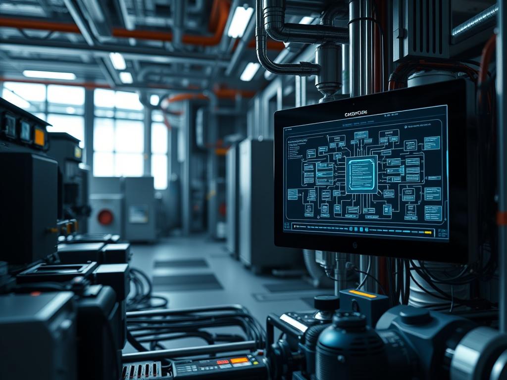
Compact system power delivery represents the critical physical Layer 0 within high-density edge computing and modular network infrastructure. As system architects compress computational density into smaller cubic footprints; such as 1U chassis or IP67-rated enclosures; the efficiency and reliability of power distribution become the primary bottlenecks for uptime. This manual addresses the transition from traditional, bulky multi-rail power supplies to high-density, compact system power delivery solutions that utilize high-frequency switching and digital management interfaces. The fundamental challenge lies in the trade-off between energy throughput and the management of thermal-inertia within confined volumes. If the power delivery subsystem fails to maintain a tight voltage tolerance, the resulting signal-attenuation on high-speed data buses can lead to catastrophic packet-loss and hardware degradation. This guide provides the technical framework for implementing, auditing, and optimizing these power systems to ensure mission-critical stability in high-concurrency environments.
TECHNICAL SPECIFICATIONS
| Requirement | Default Port/Operating Range | Protocol/Standard | Impact Level (1-10) | Recommended Resources |
| :— | :— | :— | :— | :— |
| DC Output Stability | +12VDC (+/- 5%) | Intel ATX 3.0 / EPS12V | 10 | 12AWG Solid Copper |
| Communication Interface | SMBus Address 0x50-0x5F | PMBus v1.3 | 8 | I2C Logic Controller |
| Inrush Current Limit | < 50A @ 230VAC | IEC 61000-3-2 | 7 | NTC Thermistor / Relay |
| Thermal Dissipation | -40C to +85C Operation | MIL-STD-810H | 9 | Heat-Pipe / Vapor Chamber |
| Conversion Efficiency | 92% to 94% @ 50% Load | 80 PLUS Platinum/Titanium | 9 | GaN (Gallium Nitride) FETs |
| Ripple Noise | < 120mV (p-p) @ 20MHz | IEEE 802.3bt | 6 | Low-ESR Capacitors |
| Peak Payload Latency | < 10ms Response Time | Transient Response Spec | 8 | High-Frequency Bulk Caps |
THE CONFIGURATION PROTOCOL
Environment Prerequisites:
Successful deployment of a compact system power delivery unit requires adherence to specific environmental and regulatory baselines. The facility must comply with NFPA 70 (National Electrical Code) Class 2 circuit requirements for low-voltage power distribution. The hardware must be seated in a chassis providing at least 150 LFM (Linear Feet per Minute) of airflow to counteract thermal-inertia. System administrators must possess root-level access to the Baseboard Management Controller (BMC) and have the ipmitool and lm-sensors packages installed on the host operating system. Furthermore, all integration must be performed using anti-static protocols to prevent ESD damage to the sensitive PMBus logic circuits.
Section A: Implementation Logic:
The engineering design of compact power systems prioritizes the encapsulation of electromagnetic interference (EMI) and the reduction of conversion overhead. By utilizing Gallium Nitride (GaN) transistors, these units operate at significantly higher switching frequencies than traditional silicon-based PSUs. This allows for the use of smaller inductors and capacitors without sacrificing total throughput. The implementation logic follows an idempotent methodology where the power-on sequence and voltage-rail initialization transitions must result in the same stable state regardless of the initial environment conditions. Digital telemetry via PMBus allows the system to monitor real-time power consumption, enabling the BMC to make millisecond-level adjustments to fan curves and CPU P-states, thereby preventing thermal throttling and ensuring high-concurrency performance.
Step-By-Step Execution
1. Physical Rail Verification and Impedance Audit
Before applying AC power to the Internal PSU, use a fluke-multimeter to measure the resistance between the +12VDC pins and GND on the ATX_PWR_24P or EPS_12V connectors.
System Note: This action ensures there is no dead short in the high-current path which would cause a catastrophic failure of the logic-controllers upon first boot. A reading of less than 10 Ohms indicates a potential short-circuit in the VRM stages.
2. Digital Interface Initialization via IPMI
Connect the system to a serial console and execute ipmitool sdr list to verify the visibility of the power supply sensors. If the sensors are not detected, verify the SMBus wiring and the device address.
System Note: This command queries the BMC for Sensor Data Records (SDR). It establishes the digital handshake between the OS and the power hardware. Failure here prevents the OS from managing power states or logging critical over-current events.
3. Threshold Calibration in the Kernel
Edit the /etc/sensors3.conf file to define the critical and non-critical voltage thresholds for the specific compact PSU model. Set the +12V max to 12.6V and the min to 11.4V.
System Note: Modifying the configuration for lm-sensors allows the Linux kernel to trigger an immediate shutdown via systemd-logind if voltage drifts beyond safe margins. This protects the payload on the NVMe drives and DRAM.
4. Logic Controller Daemon Selection
Execute systemctl enable –now thermald or a custom power-daemon to manage the interaction between the power delivery unit and the thermal sub-system.
System Note: This enables the user-space daemon that monitors the concurrency of CPU instructions and adjusts the power delivery profile. It reduces the latency between a heat spike and the corrective fan speed adjustment.
5. High-Load Stress Testing
Run a standardized workload such as stress-ng –cpu 0 –io 4 while monitoring the PMBus output for voltage sag. Use sensors to log the data to a CSV for analysis.
System Note: Forcing the system into a high-load state tests the transient response. This identifies if signal-attenuation occurs on the motherboard power planes under maximum throughput conditions.
Section B: Dependency Fault-Lines:
Compact system power delivery is highly sensitive to external dependencies. A common bottleneck is the use of substandard modular cabling; use only the cables provided by the Internal PSU manufacturer. Mixing cables from different vendors often results in incorrect pinouts that can fry the logic-controllers. Another frequent failure point is the firmware version of the BMC. If the BMC firmware is outdated, it may misinterpret PMBus data packets as CRC errors, leading to “ghost” power failures or unnecessary system throttles. Finally, ensure that the input AC frequency is stable; rapid fluctuations in input 50/60Hz frequency can lead to internal harmonic resonance within the GaN switching stage.
THE TROUBLESHOOTING MATRIX
Section C: Logs & Debugging:
When a power event occurs, the first point of analysis is the System Event Log (SEL). Access this via ipmitool sel elist. Look for error strings such as “Power Supply Failure” or “Voltage Sector Fault.” If the system is stuck in a boot loop, check the physical status LED on the Internal PSU. A fast-blinking amber light usually indicates an Over-Temperature Protection (OTP) trip, while a solid red light suggests an Over-Voltage Protection (OVP) or Short-Circuit Protection (SCP) lock-out.
| Error Code/String | Probable Cause | Corrective Action |
| :— | :— | :— |
| PSU_VIN_UV_FAULT | Undervoltage on AC Input | Check PDU and input breaker capacity. |
| VOUT_OV_FAULT | Logic Controller failure | Replace the Internal PSU immediately. |
| PMBus Packet Error | Signal-attenuation on I2C | Check for electromagnetic interference near the PSU. |
| Fan Speed Low | Bearing failure or obstruction | Clear debris from Internal PSU intake. |
| TEMP_CRITICAL | Excessive thermal-inertia | Increase chassis LFM or reduce CPU TDP limit. |
Path-specific log analysis can be performed by tailing /var/log/messages and filtering for ACPI events: grep -i “ACPI” /var/log/messages. This will show if the OS is receiving “Power Button Over-ride” signals from the hardware logic.
OPTIMIZATION & HARDENING
Performance Tuning:
To maximize the efficiency of compact power delivery, administrators should tune the concurrency of the VRM phases. This is often handled at the BIOS/UEFI level. Setting the VRM switching frequency to a higher value (e.g., 500kHz to 800kHz) can reduce voltage ripple, though it increases the heat overhead. For systems requiring high throughput for GPU-accelerated workloads, ensure the “Load-Line Calibration” (LLC) is set to a medium profile to prevent Vdroop during rapid load transitions.
Security Hardening:
Power delivery systems are increasingly targets for “Power-Hammering” attacks where malicious code triggers rapid power state changes to induce hardware failure. To harden the system, restrict access to the /dev/i2c-* devices using chmod 600. Only the root user or the monitoring-service should be able to communicate with the PMBus. Additionally, ensure the BMC is on a segmented management network with a robust firewall to prevent remote attackers from sending a “Power Off” command to the logic-controllers.
Scaling Logic:
Scaling a compact system involves a modular approach. Instead of a single large power source, utilize a distributed “Power Shelf” architecture where multiple 1U nodes share a rectified DC bus. This minimizes the overhead of repeated AC-to-DC conversions. As the cluster grows, ensure that the physical power cabling is sized for the aggregate payload to prevent signal-attenuation and localized heating.
THE ADMIN DESK
How do I clear a hard power-lockout?
Unplug the AC cord and wait 60 seconds for the bulk capacitors to discharge. Most Internal PSU units require a full power cycle to reset the idempotent safety state after an Over-Voltage Protection (OVP) event occurs.
Why is my PSU fan spinning but there is no video?
Check the “Power Good” (PWR_OK) signal. If the PSU detects that the voltage rails are unstable, it will not assert this signal to the CPU. Use a fluke-multimeter on the grey wire of the ATX_PWR_24P connector.
Can I use a 600W SFX PSU in a 1U server?
Only if the chassis has been modified for SFX mounting. Most 1U servers require Flex-ATX or proprietary “Cold-Plug” modules. Using the wrong form factor disrupts the intended airflow, increasing thermal-inertia and risking early component failure.
Does PMBus 1.3 support real-time energy accounting?
Yes. PMBus 1.3 allows for high-speed telemetry of input and output wattage. You can use ipmitool to pull these metrics into a Prometheus database for long-term throughput and efficiency auditing across your entire edge infrastructure.
What causes excessive 12V ripple in small systems?
Excessive ripple is usually caused by aging capacitors or high signal-attenuation due to thin PCB traces. If the ripple exceeds 120mV, it can cause packet-loss in high-speed PCIe 5.0 lanes or induce system instability during high concurrency tasks.

