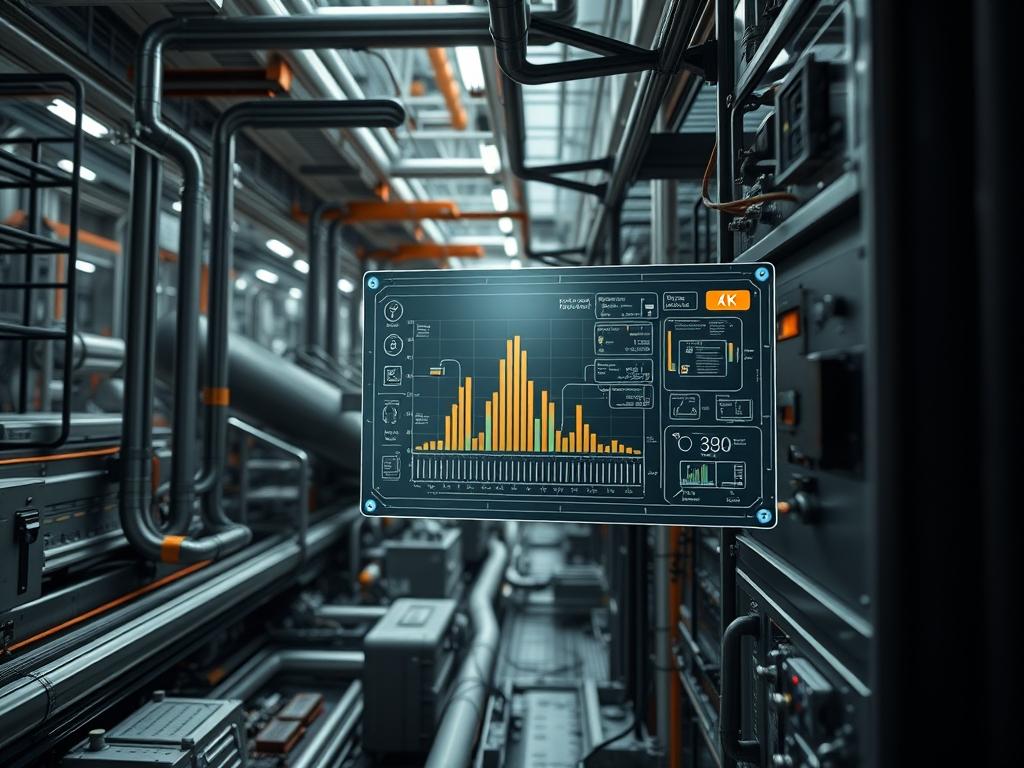
Hold up time statistics represent a critical metric in power delivery architecture; they define the temporal window between the loss of input alternating current (AC) and the point where the direct current (DC) output voltages fall below specified regulation limits. For mission critical infrastructure encompassing data centers, telecommunications, and industrial automation, this duration is pivotal for maintaining high availability. The hold up time must exceed the time required for a secondary power source: such as an Uninterruptible Power Supply (UPS) or an Automatic Transfer Switch (ATS): to engage and stabilize. Failure to maintain sufficient hold up time results in immediate system resets; this triggers uncontrolled shutdowns that can lead to data corruption or hardware damage within the storage layer. This manual focuses on the empirical measurement of hold up time statistics and the analysis of capacitor discharge data. It ensures that Power Supply Units (PSUs) comply with standards like Intel’s Power Supply Design Guide (PSDG) or the IEC 62368 series.
Technical Specifications
| Requirement | Operating Range | Protocol / Standard | Impact Level (1-10) | Recommended Resources |
| :— | :— | :— | :— | :— |
| Hold Up Time | 16ms – 21ms (Full Load) | Intel PSDG v2.0 / ATX 3.0 | 9 | Bulk Capacitor (>=330uF) |
| PWR_OK Delay | 100ms – 500ms | T3 Timing (NEC/IEEE) | 7 | FPGA Logic Controller |
| Discharge Rate | < 60% in 10ms | IEC 61000-4-11 | 8 | Passive Discharge Resistor |
| AC Input Detect | 90V – 264V AC | PMBus / SMBus 1.2+ | 6 | 16-bit ADC |
| Thermal Stability | -10C to +50C | MIL-STD-810G | 5 | Active Heat Sink / Fan |
The Configuration Protocol
Environment Prerequisites:
Testing hold up time statistics requires a controlled environment to ensure result accuracy and safety. The primary dependencies include a programmable AC power source capable of phase angle triggering; this is necessary to simulate the worst case scenario of an AC loss at the peak of the sine wave. A high speed digital storage oscilloscope (DSO) with a minimum bandwidth of 100MHz is required for capturing the discharge curve. Firmware requirements for digital PSUs include PMBus 1.2 or higher for telemetry tracking. Personnel must possess high voltage safety certifications and use isolated probes to prevent ground loops. All data logs should be stored on a filesystem with ext4 or NTFS formatting to handle the high throughput of raw sensor data during the capture window.
Section A: Implementation Logic:
The theoretical “Why” behind hold up time statistics is rooted in the energy storage capacity of the primary bulk capacitor. In a typical switch mode power supply (SMPS), the input AC is rectified to high voltage DC and stored in bulk capacitors. When AC fails, the DC-DC conversion stage continues to draw energy from these capacitors until the voltage drops below the threshold required to maintain the output rails (e.g., +12V, +5V, +3.3V). The calculation involves the formula: $E = 0.5 \times C \times (V_{start}^2 – V_{end}^2)$. To achieve a target hold up time, architects must balance the capacitor size against thermal-inertia and physical space constraints. If the discharge rate is too fast, the throughput of the secondary regulators is compromised; this leads to voltage ripples that exceed the sensitivity threshold of the motherboard VRMs.
Step-By-Step Execution
1. Primary Rig Assembly and Calibration
Connect the Chroma 63200 Electronic Load to the DC output rails of the PSU under test. Ensure that the total load reflects 100% of the rated capacity to capture the minimum hold up time baseline. Calibrate the Fluke 190 Series Scope probes to 10x attenuation.
System Note: This action sets the baseline load-inertia for the system. Calibrating the probes reduces signal-attenuation; this ensures that the captured voltage drop is not masked by noise or impedance mismatches in the probe leads.
2. AC Phase Trigger Configuration
Configure the programmable AC source to interrupt the power at the 0 degree phase angle. This represents the point of highest stress for the output capacitors. Use the systemctl stop psu-monitor command on the management server to prevent automated failover scripts from interfering with the manual test.
System Note: Triggering at the 0 degree point ensures the test is idempotent and repeatable. Stopping the management service prevents some kernel-level watchdogs from initiating a hard reset before the oscilloscope captures the full discharge curve.
3. Oscilloscope Triggering Setup
Set the oscilloscope to “Single Shot” mode. Use the AC input voltage as the trigger source: set to a falling edge at 80% of nominal voltage. Set the vertical scale to 5V per division for the DC rail and 100V per division for the AC line.
System Note: Configuring the trigger at the hardware level bypasses the latency associated with software-based polling. This allows for nanosecond-level precision in capturing the exact moment of packet-loss in the power rail.
4. Executing the Discharge Sequence
Initiate the power cut via the AC source control panel. Observe the PWR_OK signal on the DSO; it must drop at least 1ms before the DC rails fall out of regulation (typically 11.4V for a 12V rail). Record the time delta between the AC loss and the PWR_OK drop.
System Note: The PWR_OK signal acts as a hardware-level encapsulation of system health. By dropping early: it notifies the CPU to enter a low-power state and flush the cache to disk: preventing data corruption during the final discharge phase.
5. Post-Capture Data Analysis
Download the raw sample data from the DSO to a workstation. Use a script to parse the .csv data and calculate the discharge slope. Verify that the hold up time statistics meet the 16ms minimum requirement. Run chmod +x analysis_script.sh to execute the verification logic.
System Note: Managing file permissions correctly is part of the operational security of the audit. The analysis script calculates the total energy payload delivered during the discharge window: confirming the capacity of the bulk capacitors.
Section B: Dependency Fault-Lines:
Common failures in hold up time validation usually stem from aging bulk capacitors or high ambient temperatures. Electrolytic caps experience a decrease in capacitance as they age; this directly reduces the hold up time. Furthermore: if the thermal-inertia of the PSU is high: the ESR (Equivalent Series Resistance) of the capacitors increases: leading to a steeper discharge curve. Another failure point is the load tester configuration. If the concurrency of the load modules is not synchronized: the PSU may experience an artificial surge that triggers an over-current protection (OCP) shutdown before the hold up time is naturally exhausted.
The Troubleshooting Matrix
Section C: Logs & Debugging:
When hold up time statistics fail to meet specifications, analyze the internal telemetry logs stored in the PSU management controller. Access these via the /var/log/psu_telemetry.log path on the IPMI interface. Look for “Under-Voltage Warning” codes (e.g., 0x01A2) which indicate the DC rail dropped faster than the predictive logic expected.
If the DSO shows a noisy discharge curve: inspect the grounding strap of the probe. High frequency switching noise can cause signal-attenuation that makes the 5% regulation point difficult to identify. For physical fault codes: a blinking amber LED on the PSU chassis often correlates to a “Capacitor Self-Test Fail”. In digital PSUs: use the command i2cdump -y 1 0x50 to inspect the EEPROM for manufacturing data to see if the installed capacitors match the design specification.
Optimization & Hardening
– Performance Tuning: To maximize hold up time: increase the total capacitance of the bulk stage. Using capacitors with a higher voltage rating (e.g., 450V instead of 400V) allows for a larger energy reservoir within the same physical footprint. Adjust the PWR_OK delay via firmware to provide the system with more time to finalize disk writes before the rails collapse.
– Security Hardening: Implement hardware-level password protection on the PMBus interface to prevent unauthorized changes to voltage thresholds. Ensure that the fail-safe physical logic is hardwired; do not rely solely on software-based protection for capacitor discharge as software latency can be fatal in a fault condition.
– Scaling Logic: When scaling power systems for high load environments: use a N+1 redundancy configuration. This allows the load to be distributed across multiple bulk capacitor arrays: effectively increasing the aggregate hold up time of the entire rack. Monitor the throughput of each PSU to ensure no single unit is running at its thermal limit: as heat is the primary enemy of capacitor longevity.
The Admin Desk
#### How do I check the health of the bulk capacitors?
Use a specialized ESR meter or a fluke-multimeter with capacitance mode while the unit is offline. Significant deviation from the rated microfarad value indicates chemical degradation. In-circuit digital PSUs can report estimated life via PMBus health registers.
#### Why does hold up time decrease at higher loads?
Hold up time is inversely proportional to the load. At 100% capacity: the DC-DC stage draws current more rapidly from the bulk capacitors. This exhausts the stored energy faster than it would at a 50% idle load.
#### What is the relationship between hold up time and PSU efficiency?
Higher efficiency PSUs typically have better hold up time statistics. Reduced overhead in the conversion process means less energy is wasted as heat; this allows more of the stored capacitor energy to reach the output rails.
#### Can I increase hold up time via software?
Software cannot increase the physical energy storage of capacitors. However; you can optimize the system response by configuring the kernel to trigger an immediate idempotent flush of all disk buffers when the PWR_OK signal goes low.
#### What happens if the hold up time is too short?
The motherboard will lose power before the CPU completes its shutdown sequence. This causes packet-loss in the data stream and potential corruption of the file system: as the drive heads may not park correctly before voltage fails.

