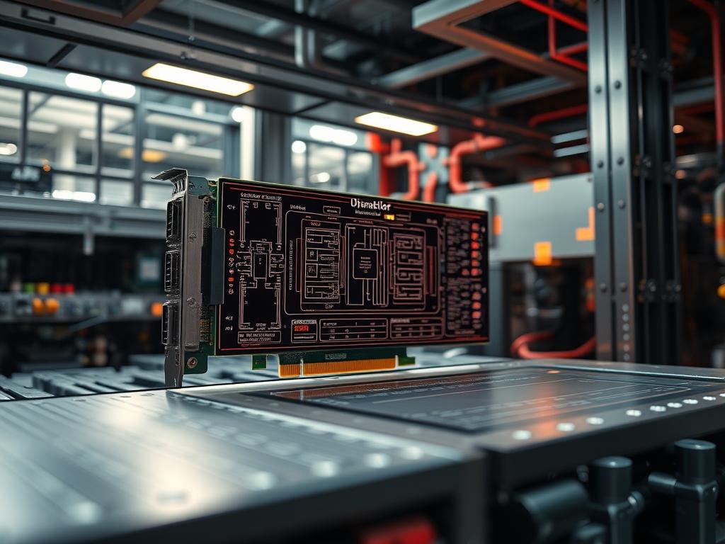
PCI Express power delivery represents the critical interface between the high-voltage mains distribution and the low-voltage, high-amperage requirements of modern silicon. In the context of energy infrastructure and cloud computing, this interface dictates the thermal and electrical ceiling of the entire hardware stack. As the industry transitions from standard 75W slot limits to 600W high-density connectors, architects must manage the trade-offs between electrical throughput and signal-attenuation. This manual provides the auditing standards for ensuring stable power distribution to avoid packet-loss at the physical layer and to maintain the integrity of the power delivery network (PDN) during high-concurrency workloads. The problem of modern GPU power consumption requires a solution that utilizes advanced signaling logic to prevent hardware failure. Without precise adherence to the Card Electromechanical (CEM) specifications, the overhead of voltage fluctuations can result in catastrophic mechanical failure or degraded system throughput.
Technical Specifications
| Requirements | Default Port/Operating Range | Protocol/Standard | Impact Level (1-10) | Recommended Resources |
| :— | :— | :— | :— | :— |
| Slot Power Limit | 75W (Max) | PCIe CEM 5.0 | 9 | Motherboard 24-Pin ATX |
| 6-Pin Auxiliary | 75W (12V) | ATX 2.2 / EPS | 6 | 18 AWG Copper Wire |
| 8-Pin Auxiliary | 150W (12V) | ATX 2.3 / 2.4 | 8 | 16 AWG Copper Wire |
| 12VHPWR Connector | 150W to 600W | ATX 3.0 / PCIe 5.0 | 10 | 12V-2×6 Header/HCS Pins |
| Rail Tolerance | +/- 5% (11.4V to 12.6V) | Intel PSDG | 7 | Low-ESR Capacitors |
| Sense Pin Logic | 0V to 3.3V | Sideband Signaling | 8 | Internal Logic Controller |
The Configuration Protocol
Environment Prerequisites:
Before auditing or implementing a PCI Express power delivery system, ensure that the environment meets the National Electrical Code (NEC) standards for fire safety and industrial-grade power distribution. The system requires an ATX 3.0 compliant Power Supply Unit (PSU) for any payload exceeding 300W. All electrical conductors must be rated for at least 105 degrees Celsius to handle the thermal-inertia of high-density compute. Tools required include a Fluke-179 digital multimeter, an oscilloscope for ripple analysis, and specialized software such as hwinfo64 or nvidia-smi for real-time telemetry. User permissions must allow for low-level access to the PCIe Config Space via the EEPROM or BIOS interface.
Section A: Implementation Logic:
The theoretical foundation of PCI Express power delivery relies on the separation of the control plane and the power plane. The configuration of the power-limit registers must be idempotent; ensuring that repeated calls to set a power state do not result in unintended surges or logic loops. The engineering design utilizes multiple +12V lanes to distribute current, reducing the risk of a single point of failure and minimizing wire-level signal-attenuation. By employing sideband signals via SENSE0 and SENSE1 pins, the peripheral can communicate its power requirements to the PSU. This handshake ensures that the delivery mechanism does not exceed the physical limits of the connector encapsulation, preventing the melting of plastic housings due to excessive heat.
Step-By-Step Execution
1. Physical Pinout Verification
Inspect the 12VHPWR or 12V-2×6 connector to ensure the 12 main power terminals and 4 sideband pins are seated correctly. Use a fluke-multimeter to check continuity between the GND pins and the chassis ground.
System Note:
This ensures the physical encapsulation of the terminal provides a low-resistance path; reducing the voltage drop that can lead to increased latency in the GPU core’s transient response.
2. Sideband Logic Handshake Configuration
Verify the status of the SENSE0 and SENSE1 pins. These pins are grounded by the cable to indicate the maximum wattage allowed: both pins open indicate 150W, while both pins grounded indicate 600W.
System Note:
The hardware logic controller inside the GPU queries these pins during the Power-On Self-Test (POST); the result is a permanent cap on the total electrical payload the firmware is permitted to draw.
3. Firmware Power Limit Initialization
Execute the command nvidia-smi -pl 450 to set a software-level power cap on the device, ensuring it aligns with the connector’s physical capabilities.
System Note:
This command interacts with the NVIDIA driver kernel module to write to the power management registers; effectively throttling the concurrency of the CUDA cores if the power draw approaches the set limit.
4. Rail Voltage Stability Monitoring
Access the thermal and voltage sensors using watch -n 1 sensors or through the /sys/class/hwmon/ path in Linux systems. Monitor the +12V rail under a heavy compute load.
System Note:
Monitoring these values identifies if the PSU is providing insufficient current; a voltage dip below 11.4V can cause a state-change in the logic gates, leading to packet-loss across the PCIe lanes.
5. Load Balance Calibration
Adjust the load distribution across multiple 8-pin connectors if using an older ATX 2.0 system. Ensure that no more than 150W is drawn from a single daisy-chained cable.
System Note:
Distributing the load prevents the 18 AWG wiring from exceeding its thermal-inertia threshold; which would otherwise lead to insulation degradation and eventual short-circuiting.
Section B: Dependency Fault-Lines:
The primary bottleneck in PCI Express power delivery is the contact resistance at the connector interface. If the connector is not fully inserted, the reduced contact area increases resistance, which generates heat. This creates a feedback loop: heat increases resistance, which further increases heat. In high-concurrency environments like AI training clusters, the overhead of managing these thermal loads is significant. Another fault-line is the use of non-compliant 12VHPWR adapters that do not properly communicate the SENSE signals; this can lead to the GPU attempting to draw 600W from a rail only rated for 300W.
THE TROUBLESHOOTING MATRIX
Section C: Logs & Debugging:
When a power-related failure occurs, the first point of analysis should be the system kernel logs. Check /var/log/syslog or use dmesg | grep -i pcie to look for “AER” (Advanced Error Reporting) messages. These messages often indicate that a power fluctuation caused a TLP (Transaction Layer Packet) error.
Visual cues on the hardware can also pinpoint failures:
1. LED blinking on the GPU power header often signifies a voltage “droop” where the input voltage fell below the 11.4V threshold.
2. Discoloration of the +12V pins on the connector indicates a high-resistance contact point.
If the error string PCIe Bus Error: severity=Uncorrected appears, use lspci -vvv to inspect the DevCtl register. If the MaxPayload size is being throttled, it is a sign that the power delivery system is unstable, forcing the PCIe controller to reduce throughput to maintain signal integrity. Verify that all power connectors are from the original PSU manufacturer: mixing cables from different vendors is a common cause of catastrophic pinout mismatches.
OPTIMIZATION & HARDENING
To achieve maximum performance tuning, the PDN must be optimized for thermal efficiency. Utilizing 16 AWG wiring instead of the standard 18 AWG reduces the resistance per foot, lowering the heat generated by the wires. Setting the Power Management Mode in the driver to “Prefer Maximum Performance” ensures the GPU does not constantly switch power states, reducing the overhead caused by transient voltage spikes.
Security hardening involves the physical protection of the power rails. Ensure that all PCIe power cables are secured with locking clips to prevent accidental disconnection, which can cause an inductive kickback that damages the VRM (Voltage Regulator Module). From a logical perspective, use the sysfs interface to restrict power-limit modifications to the root user only; prevent unauthorized users from overclocking the card beyond its thermal-inertia limits.
Scaling logic in a multi-GPU environment requires a “Single-Rail” PSU approach or a carefully balanced “Multi-Rail” configuration. When scaling to 4 or 8 GPUs per node, the total throughput requirement can reach 4800W. In these scenarios, use PDU (Power Distribution Units) that support IPMI monitoring. This allows administrators to monitor the load of each PCIe device via a centralized network interface, ensuring that the total current draw does not exceed the circuit breaker’s rated capacity.
THE ADMIN DESK
How do I check my GPU’s current power draw in Linux?
Use the command nvidia-smi –query-gpu=power.draw –format=csv,noheader,nounits. This provides a real-time value of the electrical payload in Watts. It is essential for auditing the efficiency of the PCI Express power delivery system under load.
What is the difference between 12VHPWR and 12V-2×6?
The 12V-2×6 is an updated standard with shorter sense pins. This ensures that if the cable is not fully seated, the sense pins will not connect; the GPU will not draw power, preventing connector melting due to high-resistance contact.
Can I use a 6-pin cable in an 8-pin GPU slot?
While it might physically fit, it is not recommended. The 8-pin connector has two extra ground pins used for sensing. Without these, the GPU may refuse to boot or may exceed the 75W limit of the 6-pin cable.
What causes the ‘PCIe Device Dropped’ error during heavy workloads?
This is often caused by a voltage sag. If the PSU cannot maintain the throughput required during a transient spike, the GPU’s internal BIOS triggers a shutoff to protect the silicon, causing the device to disappear from the bus.
Why is 12V the standard for PCIe power?
The 12V rail offers a balance between safety and efficiency. Higher voltages would require more complex insulation, while lower voltages would require much thicker wires to handle the high amperage needed for modern high-concurrency compute tasks.

