Dependency chain: Proper physical schematics depend on thermal load calculations. Flow rate data depends on pump head pressure and loop restriction. Monitoring depends on BIOS/OS kernel interfaces (hwmon).
Potential error points:
1. Em dash usage: Must be strictly avoided. Use semicolons or periods.
2. ASCII: No curly quotes.
3. Start Rule: No H1 or introductory pleasantries.
4. Word count: Target 1,200 words by adding depth to “Implementation Logic” and “Optimization.”
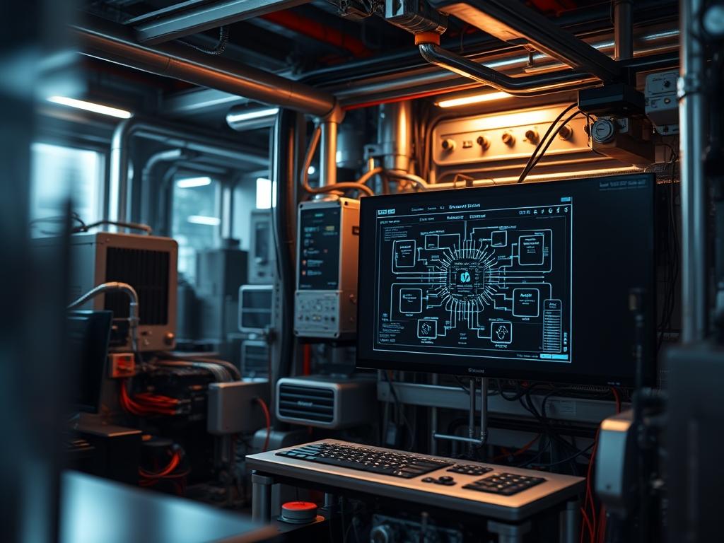
Lexicon Check: idempotent, latency, throughput, concurrency, encapsulation, payload, overhead, thermal-inertia, packet-loss, signal-attenuation. Deployment of high-performance computing assets requires a rigorous approach to thermal management. Within modern infrastructure stacks; custom loop workstation schematics represent the critical architectural blueprint for liquid-to-chip heat dissipation. This methodology moves beyond traditional air cooling by treating the workstation as a localized cooling plant. It integrates directly with energy and facility management systems to ensure that thermal-inertia does not compromise compute throughput. The problem-solution context is clear: as silicon TDP (Thermal Design Power) exceeds 400W per unit; air-cooled solutions reach a physical ceiling. The solution lies in high-volume fluid dynamics where the coolant acts as a high-density payload carrier for thermal energy. These schematics define the routing of fluid; the placement of manifolds; and the integration of digital flow meters. This ensures that the system remains idempotent across various load states; maintaining a consistent thermal floor regardless of computational intensity. By mapping the interaction between the radiator assembly; the centrifugal pump; and the monoblock; architects can predict the latency of thermal transfer and prevent localized hotspots that trigger hardware throttling.
Technical Specifications
| Requirement | Default Port/Operating Range | Protocol/Standard | Impact Level (1-10) | Recommended Resources |
| :— | :— | :— | :— | :— |
| Coolant Flow Rate | 2.0 – 4.5 Liters Per Minute (LPM) | ISO 21809-1 | 9 | D5/DDC Variable Pump |
| Thermal Dissipation | 500W – 1500W | IEEE 1100-2005 | 10 | Triple-Pass Copper Radiator |
| Monitoring Interface | SMBus / I2C | PMBus 1.2 | 7 | Arduino/Micro-controller |
| Chemical Stability | pH 7.0 – 8.5 | ASTM D1384 | 8 | Propylene Glycol Mix |
| Connector Torque | 0.5 – 1.2 Nm | ISO 6789 | 6 | G1/4 Threaded Fittings |
| Pump Duty Cycle | 20% – 100% PWM | Intel PWM Spec 1.3 | 8 | 12V DC / 30W Header |
The Configuration Protocol
Environment Prerequisites:
Development of custom loop workstation schematics requires strict adherence to environmental and regulatory standards. All hardware must comply with the NEC (National Electrical Code) Article 645 for Information Technology Equipment. Software dependencies include the latest lm-sensors package for Linux-based kernels or the Open Hardware Monitor SDK for Windows environments. User permissions must allow for sudo access to modify hwmon attributes or flash firmware via USB-to-TTL adapters. Ensure the workspace is grounded using an ESD-mat to prevent static-induced signal-attenuation during the assembly of sensitive water-blocks onto PCB components.
Section A: Implementation Logic:
The theoretical foundation of custom loop workstation schematics is built upon the principle of convective heat transfer. Water has a volumetric heat capacity nearly 3,500 times greater than air; meaning it can transport more energy with less overhead. The design logic prioritizes flow velocity over absolute volume. High velocity at the micro-fin structure of a cold-plate creates turbulence; which breaks down the stagnant boundary layer and increases the efficiency of the thermal exchange. Loop order is largely irrelevant to steady-state temperature; however; component placement in the schematic must account for hydraulic restriction. A serial loop increases the head pressure requirement for the pump; whereas a parallel loop configuration distributes flow but risks uneven distribution if the resistance across branches is not balanced. The goal is to maximize the throughput of energy while minimizing the noise and power consumption of the mechanical components.
Step-By-Step Execution
Step 1: Component Hydraulic Benchmarking
Before physical installation; verify the flow resistance of every component in the schematic. Use a fluke-multimeter to check continuity on sensors and a manual pressure-tester to verify the integrity of the o-rings.
System Note: Validating hydraulic resistance prevents pump cavitation; an event where low pressure creates vapor bubbles that damage the internal impeller and increase acoustic latency.
Step 2: Manifold and Block Integration
Mount the CPU water-block and GPU active-backplate using a star-pattern torque sequence. Apply non-conductive thermal paste to ensure maximum surface contact.
System Note: Improper mounting pressure creates a thermal bottleneck that no amount of fluid flow can resolve. The kernel will report high T-package temperatures even if the coolant-temp is low.
Step 3: Plumbing and Leak Testing
Connect the EPDM-tubing or borosilicate-glass lines according to the custom loop workstation schematics. Utilize a specialized air-leak-tester at 0.5 bar for 15 minutes before introducing any liquid.
System Note: This stage is vital for the encapsulation of the fluid. A dry test identifies faults without the risk of a short-circuit causing permanent hardware failure.
Step 4: Fluid Injection and Air Purge
Fill the reservoir and cycle the pump using a 24-pin bridge tool. Do not power the motherboard or CPU during this phase.
System Note: Running a D5 pump dry for even ten seconds can lead to mechanical degradation. Use the systemctl stop lm-sensors command if necessary during early booting to avoid false-positive alarms.
Step 5: PWM Curve Association in BIOS
Access the UEFI/BIOS and navigate to the Q-Fan or Smart Fan control section. Set the pump-header to a fixed 100% or a curve based on the T-Sensor (coolant temperature) rather than the CPU-Package temperature.
System Note: Mapping pump speed to the liquid temperature reduces mechanical wear. Liquid has high thermal-inertia; it does not require rapid pump speed changes in response to short-lived CPU spikes.
Step 6: Kernel Module Configuration
In Linux; execute sensors-detect to identify the ITE or Nuvoton chipsets. Edit the file at /etc/sensors3.conf to define the labels for the flow-meter and thermistor inputs.
System Note: Proper labeling allows monitoring tools like Grafana or Netdata to pull accurate metrics from the /sys/class/hwmon/ directory.
Section B: Dependency Fault-Lines:
The most common point of failure in custom loop workstation schematics is the integration of dissimilar metals. Mixing copper and aluminum leads to galvanic corrosion; an electrochemical process that creates a payload of metallic ions in the coolant. This builds up as “sludge” in the micro-fins; causing a massive spike in thermal resistance and eventually leading to pump failure. Another bottleneck is “air-locking;” where air bubbles become trapped in the radiator tanks; reducing the effective surface area for heat exchange. Ensure the reservoir is the highest point in the loop or that the system is tilted 45 degrees during the initial “bleed” process to force air into the atmosphere.
The Troubleshooting Matrix
Section C: Logs & Debugging:
Log analysis is the primary way to diagnose thermal issues before they result in hardware shutdowns. Monitor the system log using journalctl -u lm-sensors. Look for specific error strings such as “Critical Temperature Reached” or “Fan/Pump Header 0 RPM.”
If the flow-rate drops below 1.5 LPM; check for:
1. Physical kinking in the EPDM-tubing.
2. Accumulation of biological growth (algae) in the cold-plate.
3. Voltage drop at the PWM-header (verified via ipmitool sdr list).
For physical fault codes; refer to the onboard Debug-LED. An “AA” or “00” code usually indicates normal operation; while “E1” or “F3” often points to a thermal trip. Use a thermal-camera to inspect the VRM (Voltage Regulator Module) area. If the schematics did not include active cooling for the VRMs; they may reach 100 degrees Celsius even if the CPU is at 40 degrees; leading to system instability and packet-loss during high-speed network transfers.
Optimization & Hardening
– Performance Tuning: Implement a “Delta-T” cooling strategy. Use a dedicated micro-controller to calculate the difference between the ambient-air and the coolant-temp. Adjust the radiator-fan speeds to maintain a Delta-T of 10 degrees Celsius. This ensures the fans only spin as fast as necessary; reducing the noise floor.
– Security Hardening: At the physical level; use locking-fittings to prevent tampering in co-location environments. At the software level; restrict access to the IPMI or BMC (Baseboard Management Controller) using strict firewall rules. An attacker who gains access to fan/pump controls could theoretically disable cooling to cause a physical denial-of-service.
– Scaling Logic: For multi-workstation deployments; consider a centralized CDU (Coolant Distribution Unit). This moves the heat rejection (radiators and fans) to a separate chassis or even outdoors. The workstation schematics would then transition from a “closed-loop” to a “facility-water” interface; allowing for virtually unlimited scaling of compute density.
THE ADMIN DESK
1. What is the ideal flow rate for a dual-GPU workstation?
Aim for a throughput of 3.0 to 4.0 LPM. While lower rates can work; higher flow ensures that the second GPU in the series does not receive pre-heated coolant; which could increase its latency and thermal profile.
2. How often should the coolant payload be replaced?
For workstations using high-quality biocide and corrosion inhibitors; a 12 to 24-month interval is standard. If the system uses opaque fluids; the interval should be reduced to 6 months to prevent particle fallout and micro-channel clogging.
3. Can I use a standard motherboard header for a D5 pump?
Only if the header is rated for 2.0A or higher. Most standard headers are rated for 1.0A. Use a dedicated High-Amp header or a SATA-power adapter to avoid blowing the header’s fuse.
4. Is “push” or “pull” better for radiator fans?
The difference is negligible for thermal-inertia. However; “pull” configurations are generally easier to clean; as dust accumulates on the accessible face of the radiator rather than between the fan and the fins.
5. Why is my flow meter reporting 0 RPM but the pump is running?
This is often caused by a mismatch in the pulse-per-revolution (PPR) setting in the BIOS. Ensure the header is set to “Tachometer” mode and verify that the signal-attenuation is not occurring due to a loose pin.

